Binary, Decimal and Gray Code Table:
Binary to Gray Code Converter:
This same technique can be applied to make gray to binary converter. There will be 4 input bits, which represent binary and 4 output bits which represent equivalent gray code.
Since we are creating binary to gray code converter so, we need to find expressions for each gray code output in terms of input binary bits.
So, there will be four output bits  . For these output bits the input will be different combinations of
  based on minimized expression.
Karnaugh Maps:
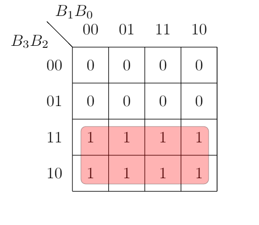
A3:

Minimized expression from the above k map,

A2:

Minimized expression from the above k map,

But, the expression of XOR Gate is (Let, A and B be the inputs),

[Note: This is not related to this problem but, only showing how XOR can be made from And, Or, Not gates]
[Note: This is not related to this problem but, only showing how XOR can be made from And, Or, Not gates]
Similarly,it can be shown that,

If XOR gate is not available then the former expression can be used with and, or and not gates to design the gray code converter.
A1:

Minimized expression from the above k map,

Similarly,it can be shown that,

A0:

Minimized expression from the above k map,

Similarly,it can be shown that,

Circuit Diagram using XOR gates:

Circuit Diagram without using XOR gates:


